

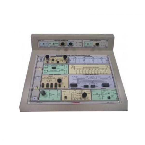
Description
Features:
• Built-in FUNCTION GENERATOR
• Built-in pulse generator.
• Built-in D.C. Regulated power supplies ( +/-12V, +5V).
• Variable simulated line length. (5 -miles & 10-mile co-axial cable).
• Variable distributed line attenuation.
• Simulated 50 ohm line (LC Network):
• Standing wave display:
• Built-in noise generator:
• Comprehensive instruction manual.
List Of Experiments:
Study of
• Attenuator and characteristic impedance.
• Effect of line resistance & capacitance on simulated transmission lines.
• The lumped parameter line.
• Matching using a pulse input.
• Noise in communication.
• The effect of ac coupling
• Reflection with a sine wave input.
• Standing waves
• Low pass filter effect
• Oscillators
Introduction:
SIMULATED 50-OHM LINE:
H and 3.3nf respectively). The simulated line is divided into 24 sections, in order to allow you to monitor signals at various points along its length. It is this simulated transmission line that you will use for most of the practical experimentation in this laboratory manual.This block simulates a transmission line with a characteristics impedance of 50-ohms, using a network of inductors and capacitors, (10
STANDING WAVE DISPLAY:
The standing wave display circuit allows you to display any “standing”waves that may be present on the 50-ohm lines, using your oscilloscope. Trigger O / P and clock O / P can also be observed.
TERMINATION UNIT:
fd to allow you to experiment with different termination conditions at the end of the transmission line.This block provides a 100-ohm variable resistor and a capacitor of value .047
PULSE GENERATOR:
The pulse generator section circuit generates a digital pulse train for transmission over the transmission line. The frequency and pulse width of the pulse train may be varied by means of the PULSE WIDTH control.
NOISE GENERATOR:
This block can be used to show how electrical noise can affect signals received over transmission line. The circuit generates wide band electrical noise, whose amplitude may be adjusted by means of the NOISE AMP control.
FUNCTION GENERATOR:
A sine square generator with frequency range from 1 KHz to 100 KHz, which can be adjusted by means of Frequency and Amplitude control.
SUMMING AMPLIFIER:
The summing amplifier adds the voltage applied to its IN socket to the signals from the pulse generator tune and noise generator circuits. The resulting voltage is then amplified by the summing amplifier, whose gain may be adjusted from + 1 to approximately + 9 by means of the GAIN control. The final output voltage appears at the output terminal and is used to drive the transmission line. When the DC / AC switch is in the DC position, any DC components that are present at the inputs of summing amplifier will be amplified and will appear at the output terminal. If this switch is in the AC position, any DC component, that are present at the inputs of the summing amplifier will be amplified and will appear at the output terminal. If this switch is in the AC position, any DC component will be removed from the output of summing amplifier.
PULSE SQUARER:
The block is used to “square up” the edges of digital puls es that have been distorted by their passage over the transmission line. The pulse width can control through adjustable comp level potentiometer.
BUFFER:
A Buffer circuit is provided with high input impedance and low output impedance to buffer analog signal wiring at the end of transmission line.
SIMULATED TRANSMISSION LINE CABLE (RC NETWORK):
You can observe the effect of the line’s resistance and capacitance on a square wave signal.
ATTENUATOR:
A 12dB T Network is obtained by cascading 1,2,3, 6 dB n etworks. The input and output impedance of 600 ohms are provided for attenuation of the network. This line differs from 50-ohm simulated lines in that it is purely resistive, while other two contain reactive elements.
Power Supply
Voltage range : AC 100V – 230V.Frequency Range : 50 – 60Hz.
Housing
Enclosed in a metal cabinet (CNC machined with mat Finish)
Dimension
45cm x45cmx18cm
Weight
6 Kg (approx).
This trainer is a glass-epoxy printed circuit board and all the symbols screen-printed on the front panel so that it enables the student to conduct the experiments easily
Accessories:
• 2mm multi coloured moulded patch cords with daisying facility.
Step-By-Step detailed instructions are provided with the instruction manual.
Reviews
There are no reviews yet.