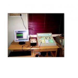
Description
FEATURES OF CIETEC TRAINER:
CIETEC comes as two units (Analogue [CIETEC-1] and Digital [CIETEC-2] Communications).
1.CIETEC-1 unit consists of the signal sources mentioned below:
AF OSCILLATOR
Output Waveforms
Sine.
Frequency Range
• X1->20Hz to 200Hz.
• X10->200Hz to 2KHz.
Amplitude Range
0 –10V(P-P).
RF OSCILLATOR
Output Waveforms
Sine /Square.
Frequency Range
• X1->2KHz to 20KHz
• X10->20KHz to 200KHz
Amplitude Range
0-5V (P-P).
2.CIETEC-2 unit consists of the signal sources mentioned below:
AF OSCILLATOR:
Output Waveforms
Sine /Square
Frequency Range
• X1->20Hz to 200Hz
• X10->200Hz to 2 KHz
Amplitude Range
(0 – 10V)(P-P)
.CLOCK GENERATOR:
FREQUENCY RANGE
FREQUENCY VARIATION
X0.1
2Hz-16Hz
X1
8Hz-200Hz
X10
80Hz-1.2KHz
X100
800Hz-12KHz
X1K
8KHz-100KHz
Output Waveform:
CLOCK
Clock Frequency vary with Frequency control Potentiometer.
PULSE
Clock Pulse width vary with Pulse width Control potentiometer.
1.5 MHz SYNC PULSE O/P
Varies from1.1MHz to1.5MHz (Frequency control potentiometer provided for FINE frequency adjustment)
3.DAQ USB DETAILS:
• Small, portable multifunction data acquisition devices.
• 12 or 14-bit input resolution, at up to 48 kS/s.
• Built-in, removable connectors for easier and more cost-effective connectivity
• 2 true ADC Analogue inputs for accurate measurements.
• Input range – ±10, ±5, ±4, ±2.5, ±2, ±1.25, ±1 V
• Maximum working voltage – ±10 V
• Over voltage protection – ±35 V
• FIFO buffer size – 512 B
• Timing resolution – 41.67 ns (24 MHz time base)
• Timing accuracy – 100 ppm of actual sample rate
• Input Impedance – 144 k½
• Trigger source – Software or external digital trigger
• System noise – 0.3 LSBrms (±10 V range)
4.SYSTEM REQUIREMENTS
RAM
256MB
Screen Resolution
1024 x 768 Pixels
Operating System
Windows XP
Hardware Interface
USB 6009 DAQ Card
Supporting Software
• (1).JDK1.5 toolkit (provided with the CIET package)
• (2).USB DAQ Card (provided with the CIET package)
• (3).PC SCOPE (provided with the CIET package)
5.CIET trainer comes with:
• CIETEC1
• CI/ETEC2
• USB DAQ CARD
• CIET SOFTWARE CD
• VIDEO CD
• USB DRIVER CD
• STEP-BY-STEP INSTRUCTION MANUAL
LIST OF EXPERIMENTS:
ANALOGUE COMMUNICATION [CIETEC-1]:
• Study of Amplitude Modulation and Demodulation
• Study of Frequency Modulation and Study of Phase Locked Loop (PLL) FM Demodulator
• Study of Balanced Modulation.
• Study of Pulse Amplitude Modulation and Demodulation.
DIGITAL COMMUNICATION [CIETEC-2]: PPM/PWM modulation/demodulation
• PCM modulation/demodulation.
• Time Division Multiplexer.
• FSK transmitter.
• FSK receiver.


Reviews
There are no reviews yet.